...So I came up with a fully-differential form of the Deboo Integrator we used to servo the THAT1510.
You may recall that the THAT1510 provides a single-ended output to feed the servo but requires a differential output (at least in this topology) to feed the preamp inputs: viewtopic.php?f=6&t=14&start=114
The THAT1570 and THAT1583 have differential outputs and also require a fully-differential servo to feed the 1570 inputs.
Deboo describes a differential input for his grounded capacitor integrator in this 1969 patent drawing. This topology provides a single-ended output.
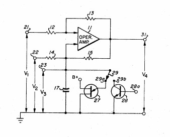
Deboo Differential Input Single-Ended Output Grounded Capacitor Integrator, 1969, US Patent 3470495.
Read the 1969 patent by Gordon J. Deboo here: http://www.waynekirkwood.com/images/pdf ... 470495.pdf
What I needed was a floating capacitor, differential input and output, single-capacitor, Deboo integrator.

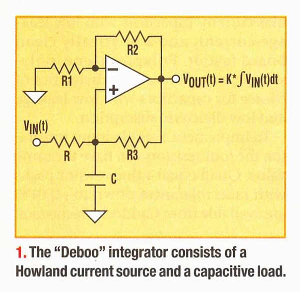
A Fully-Differential Floating Capacitor Deboo Integrator to Servo the THAT1570 Differential In/Differential Out Mic Preamp
Unlike Deboo's differential input topology, the capacitor in the "fully-differential Deboo" floats.
Deboo's topology is modified to become fully differential using an instrumentation amp that provides positive feedback into both input legs.
The INA DC differential gain (without positive feedback) is "2." [1+{(10K+10K)/20K}]
The common mode gain is "1."
Though it does not remove the 1570's "-1" Vbe common mode offset, the differential offset error is held very low over a ~60dB gain range and eliminates the requirement for a Cgain capacitor.
I'm typically seeing <15mV output Vos at low gain and <3mV at high gain in a non-optimized test circuit.
I'm temporarily using 10K Rfb (x2) for the 1570 (which is on the high side) in order to re-use the stepped gain switch I built for the 1510.
Note that the non-inverting response of the requires the outputs to be cross-coupled to opposing inputs i.e. the integrator half for Out 1 connects to the In 2 current injection resistor. (100K Rinj, 1K1 Rbias both not shown.)
For it to have the same response as the 1510 circuit I think the 1uF needs to be lowered to 0.47uF since there are now 1M resistors in both legs.
I'm going to keep playing with this because I think it has a lot of potential.
THAT does not show a servo circuit for the 1570 or 1583 and this might fill the bill.
Edit: I think I also see a simple transformation to the "inverting" configuration.